
So many pixels, so few bytes
Remember back in 1990? No multitasking, DOS applications running in 16 bit mode with all privileges, setting VESA Mode X was two machine instructions, and putting a pixel on the screen was a single write to a memory location?
Remember 2016? Big, fat operating systems with big, fat drivers, no hardware control, and putting a pixel on the screen requires talking to a graphics server and lots of graphics API calls?
- Booted directly by GRUB
- Runs at least in 32 bit mode
- Activates a high-res graphics mode (at least 1024×768 and 32 bit depth)
- Puts at least one pixel on the screen
TL;DR
The answer is: 66 bytes.
This is the assembly code (GNU syntax):
#define	MULTIBOOT_MAGIC		0x1BADB002
#define	MULTIBOOT_FLAGS		0x00010007
.text
.code32

.globl start, _start

start:
_start:
	jmp	multiboot_entry_point
	.align	4

multiboot_header_struct:
	.long	MULTIBOOT_MAGIC
	.long	MULTIBOOT_FLAGS
	.long	-(MULTIBOOT_MAGIC + MULTIBOOT_FLAGS)
	.long	multiboot_header_struct
	.long	_start
	.long	_edata
	.long	_end
	.long	multiboot_entry_point
	.long	0
	.long	1024
	.long	768
	.long	32

multiboot_entry_point:
	mov	0x4c(%ebx),%eax
	mov	0x28(%eax),%eax

	movl	$0xFF0000, (%eax)

loop:	jmp	loop
This is the necessary GRUB2 configuration:
insmod vbe
insmod multiboot
insmod iso9660

menuentry "grub-inrayders" {
	multiboot /boot
}
Build it with:
gcc -ffreestanding -m32 -nostdinc -nostdlib -I. -O2 -W -Wall -c boot.S
gcc -Wl,-N -Wl,-Ttext -Wl,100000 -Wl,--build-id=none -o boot.elf boot.o
strip -s -R .comment -R .gnu.hash -R .gnu.version -R .dynsym -R .rel.text -R .dynstr -R .dynamic -R .interp --strip-unneeded boot.elf
objcopy -O binary boot.elf boot
How it works
I’m totally cheating here, but that’s what we did back then too: You didn’t really set a graphics mode with just two machine instructions, the VESA BIOS did it for you. You didn’t initialize the hardware, DOS did it for you (to some degree).
The biggest space saver is GRUB2, because it supports the Multiboot. Multiboot will set up a lot of things for you if you provide a Multiboot header. I am using the following things:
- GRUB2 loads my binary, so no need for my own bootloader.
- GRUB2 sets up 32 bit protected mode, so no need to switch manually.
- GRUB2 sets up the VESA graphics mode (this is a little known feature) using the VESA BIOS Extensions and, if the right bits are set, hands over a linear framebuffer address. Writing pixel data to the framebuffer immediately puts pixels on the screen.
Let’s take a step-by-step tour through the code:
multiboot_header_struct:
	// Magic
	.long	MULTIBOOT_MAGIC
	// Flags
	.long	MULTIBOOT_FLAGS
	// Checksum
	.long	-(MULTIBOOT_MAGIC + MULTIBOOT_FLAGS)
	// Header address
	.long	multiboot_header_struct
	// Load start address
	.long	_start
	// Load end address
	.long	_edata
	// BSS End address
	.long	_end
	// Entry point address
	.long	multiboot_entry_point
	// Graphics mode (linear framebuffer)
	.long	0
	// Graphics width
	.long	1024
	// Graphics height
	.long	768
	// Graphics depth
	.long	32
The Multiboot header is a data structure at the beginning of the binary. If GRUB2 sees the right magic value, it will interpret the data structure. The flags field needs to be set according to the specification, in my case e.g. I set bit 11 to tell GRUB that I want a graphics mode and the corresponding header fields have been set. Additional fields hold various important pointers, e.g. the start address of the actual machine code.
The most important fields for me are the four last ones. Graphics mode 0 requests a linear framebuffer instead of bank switching, width, height and depth are self-explanatory. Note that GRUB2 will only set the mode correctly if the vbe module is loaded, other graphics modules will interfere and the buffer is not set up.
multiboot_entry_point:
	mov	0x4c(%ebx),%eax
	mov	0x28(%eax),%eax
This is the start of the actual machine code. The Multiboot specification will set up the environment so that the EBX register points to a special data structure with additional system information:
typedef struct multiboot_info {
	uint32_t	flags;

	uint32_t	mem_lower;
	uint32_t	mem_upper;

	uint32_t	boot_device;

	uint32_t*	cmdline;

	uint32_t	mods_count;
	uint32_t*	mods_addr;

	uint32_t	syms[4];

	uint32_t	mmap_length;
	uint32_t*	mmap_addr;

	uint32_t	drives_length;
	uint32_t*	drives_addr;

	uint32_t	config_table;

	uint32_t	bootloader_name;

	uint32_t	apm_table;

	uint32_t*		vbe_control_info;
	vesa_mode_info_t*	vbe_mode_info;
	uint32_t		vbe_mode;
	uint32_t*		vbe_interface_seg;
	uint32_t*		vbe_interface_off;
	uint32_t		vbe_interface_len;
} __attribute__((packed)) multiboot_info_t;;
The vbe_mode_info field is a pointer to VESA BIOS Extension data structure, which has another field that holds a pointer to the linear framebuffer allocated by GRUB2. So mov 0x4c(%ebx),%eax dereferences right field in EBX pointer and mov 0x28(%eax),%eax the second one, with the linear framebuffer address ending up in the EAX register.
movl $0xFF0000, (%eax)This line draws a red pixel (bits 16 to 23 are the bits for the red color channel in 32 bit color depth) to the first entry of the linear framebuffer. And now to the most important part:
loop: jmp loopNothing left to do, loop forever.
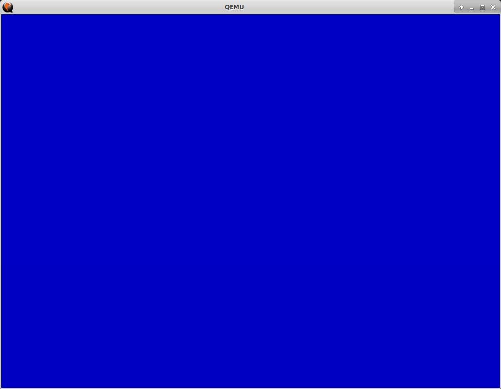
Demo
For the demo I wanted a bit more than just a single pixel, so the following piece of code fades from a full, black screen to a full, blue screen in a loop:
multiboot_entry_point:
	// Get the VBE framebuffer address into EAX
	mov	0x4c(%ebx),%eax
	mov	0x28(%eax),%eax

	// Keep the color in EDX
	xor	%edx, %edx

main_loop:
	// Reset the pixel counter in ECX
	xor	%ecx, %ecx

	// Increase the color
	inc	%dl

pixel_loop:
	// Draw current pixel
	mov	%edx, 0(%eax,%ecx,4)

	// Jump to next pixel
	inc	%ecx

	// Have all the pixels in this frame been drawn?
	cmpl	$786432, %ecx

	// Yes, draw next pixel
	jl	pixel_loop

	// No, jump to next frame
	jmp	main_loop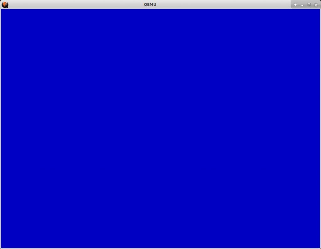
If you want to try it for yourself, download the pre-built ISO image. Run with:
qemu-system-x86_64 -cdrom demo.iso